Shadows in Section: Revit – Theater Perspective Section

This tutorial will show you how to use shadows and ambient shadows in Revit to enhance a section, using Photoshop. I’ll be using a perspective section from my master’s thesis project: The Performance of Light, to demonstrate these techniques. This tutorial was inspired by a similar section drawing of the Taipei Performing Arts Center by OMA.
Software Required: Revit, Adobe Photoshop
Time Required: 30-60 Minutes
Difficulty: Advanced
Create a Section
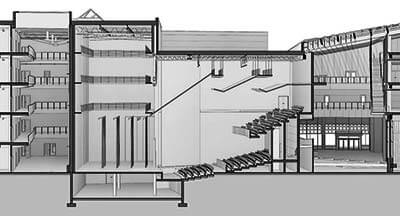
You’ll first need to start with a section view. It can be a 2D view or perspective, which is what I’m using. If you’d like to know how to make perspective sections in Revit, view this tutorial. Figure 1 shows my section with a hidden line visual style, without any shadows or adjustments.

Figure 1: Perspective section view in a basic hidden line visual style.
Create the Base Layer
Before using this as our base layer, let’s make some adjustments. Open up the graphic display options and turn on smooth lines with anti-aliasing. In the visibility/graphics overrides, I set the cut pattern to a solid dark gray for the floors, walls and structural foundations, and black for the structural framing. This allows the cut portion of the building to read much better. Now export this image out as your base. I exported as a TIFF file, with a horizontal size of 14,250 pixels.

Figure 2: Base image with gray and black poche.
Turn on the Shadows

Figure 3: Shadow strength – 10.
We’ll export out a series of images with different shadow settings, and then use Photoshop to blend them together. Open up the graphic display options, and turn on shadows and ambient shadows. Under the lighting tab, I set mine to sun: 100, ambient light: 100, and shadows: 10 to start.

Figure 4: Shadow strength – 20.
For the sun setting, you can set it to sunlight from the top left/right or still, to accurately reflect the site location and time. The shadow strength under the lighting conditions will control the darkness of the scene, while ambient shadows will add the ambient occlusion effect to the view.

Figure 5: Shadow strength – 75.
Using these settings, I exported three images with a shadow strength of 10, 20 and 75.
Blend in Photoshop
Bring all of the exported images into Photoshop, and layer them with the weaker shadow images on the bottom, and the stronger ones on the top. I actually used the shadows 10 image as the base image, and saved the shadowless hidden line layer for later use. Next, apply a mask to each layer and fill each mask with black for each mask above your base layer. The masks will be used to reveal the darker layers in the desired areas. In my case, the closed-off mechanical spaces are the darkest, while the theater spaces are the next darkest. Figure 6 shows the layer arrangement of the exported Revit images, and the masks used for each one.

Figure 6: Layer arrangement and masks of Revit images.
A breakdown of how I masked each layer is below.
Shadows 10 Layer
The ground details to the right of the building were masked out, while 50% gray was applied to the rest of the areas, to brighten them up.

Figure 7: Masked areas on the shadow 10 layer.
Shadows 20 Layer
Starting with a black mask, the two hallways were fully revealed to darken them, while 50% gray was applied to the lower room and recital hall above.

Figure 8: Masked areas on the shadow 20 layer.
Shadows 75 Layer
Since this layer is the darkest, it was used to mask in mechanical spaces, plenums, and other areas which receive little light. The strength of the mask is shown in figure 6.

Figure 9: Masked areas on the shadow 75 layer.
Shadows 75-Opacity Layer
The two theater spaces were fully revealed on the shadow 75 layer, except that the layer was set to 60%, so they would not be as dark as the spaces above.

Figure 10: Masked areas on the shadow 75-60% opacity layer.
Color Overlays
To emphasize the performance and daylit areas, I used color overlays. The blue over the theaters was achieved by applying a hue/saturation adjustment layer to the shadow 75-opacity layer, with the colorize box checked, and the hue slider dragged to blue. The yellow over the atrium’s was done in the same way as the lights described below.

Figure 11: Perspective section with color overlays.
Lighting
Since this building is designed for performance-related programs, I wanted to show the use of artificial lighting in the theater spaces. Using the following procedure, I added spotlights in the two theater spaces, as well as general down lights in the upper recital hall.
Use the elliptical marque tool and select the area on the ground in which the light will illuminate. Switch to the polygonal lasso tool and trace the path of the light to the ceiling, adding to the original selection. Fill this selection with white, and then apply a mask to the layer. Use a black to white gradient and click and drag from the top of the light and then release below the bottom of the light. It may take some trial and error to get the gradient right. Then lower the opacity of the layer to suit your need.

Figure 12: Procedure for drawing a light in Photoshop.
Touch Ups & Figures
To darken the cut portions of the building, I brought in the original base image without shadows and placed it above the other layers, while setting the blend mode to multiply.
Adding the figures can be done in Photoshop or Illustrator. I opened the Photoshop document in Illustrator and added them there since I had a lot of people vector files to draw from.

Figure 13: Figures added in Illustrator.

Figure 14: The completed perspective section.
You might also like