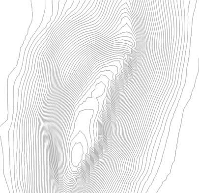
This tutorial will show you how to create contour lines from terrain in SketchUp
Software Required: SketchUp
Time Required: 5-10 Minutes
Difficulty: Intermediate
If you don’t have the time or knowledge to search for and download contour lines from online GIS or topographic data sources, there’s a relatively quick and simple way to generate contour lines in SketchUp from imported Google Earth Terrain. Follow the steps below to find out how.
1. Open up SketchUp and click on the add imagery icon. It looks like this: ![]()
2. Locate the area you want, and then click on select region. Move the four pins around until you have your desired selection, and click on grab area.
3. You’ll now draw a rectangle to define the area in which the contours area generated. Then while the move tool is selected, hit the control/command key to enable a copy of the selection. Move the copied rectangle the distance you decided on before for the space between contours. In this example, I choose 10 feet. If you are not worried about using the finished contours at a certain scale, then skip to step 4, if not, see one of two options below.
a. If you have SketchUp Pro: You’ll be able to export the lines to many different formats. If exporting to a PDF, options to set the scale will appear when saving the file. Other formats such as AutoCAD can be exported at full scale and then scaled for use in that program.
b. If you don’t have SketchUp Pro: You’ll have to export as an image at the end. The dimensions of the image will have to match a predetermined area in order for the scale to match. Here’s an example: Say you want to print the contour lines at 1/16 scale onto a 11″ by 17″ sheet of paper. Ignoring the margins, the full size dimensions work out to 176′ by 272′. Since 11″ x 16 = 176, and 17″ x 16 = 272. Draw the 176′ by 272′ foot rectangle over the terrain you wish to include and follow the steps below. When you go to export the image, assuming the finished document is being printed at 300 dpi, the minimum resolution of the exported image should be at least 3300 by 5100 pixels. After the image is exported, bring it into a raster or vector based software, and make a document that is 11 by 17 inches in size. Then stretch your contour image so that the contour lines meet all four edges of the document. The scale should now be preserved.
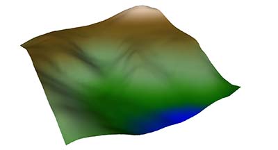
4. Turn on the 3D terrain by clicking on the toggle terrain button ![]() , and keep copying the rectangles up until they fully cover the terrain. Make sure they also extended below the first rectangle you drew, since the terrain’s highest point may be located at the origin.
, and keep copying the rectangles up until they fully cover the terrain. Make sure they also extended below the first rectangle you drew, since the terrain’s highest point may be located at the origin.
 5. Now right click the terrain geometry and unlock it. Then double click to edit the contents. Select all the geometry, then intersect the geometry with model (right click > Intersect Faces > With Model).
6. Double click outside the boundary of the group to exit. Then either delete or hide all of the rectangles. You should have something that looks like the image below.
Change the view style to wireframe (View > Face Style > Wireframe) so the geometry looks like this.
 7. To get a good view for exporting, change the camera to parallel projection (Camera > Parallel Projection), and top view (Camera > Standard Views > Top).
You can either export the image as a high resolution image, or a vector file in the form of a PDF or AutoCAD file (Pro version only).


