This tutorial will show you how to create an annotated axonometric diagram / drawing in Revit, using the section box, visibility/graphics overrides, graphic display options, and text annotations.
Software Required: Revit
Time Required: 15-20 Minutes
Difficulty: Intermediate

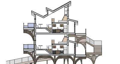
Figure 1: Section box in 3D view.
Setup Camera
Duplicate the default 3D view, or another view of your choosing. Turn on the section box, and use the control handles to adjust the extents of the box. Figure 1 is what my 3D section looks like in a shaded visual style, cutting through the stair and roof.

Figure 2: Using ambient shadows and lighting settings.
Adjust Visual Style and Graphic Overrides
You may not want all of the model categories on in the view. In my view, I turned off railings and ceilings, as I’m focusing more on the stair structure. Model elements can either be hidden in the model categories in the visibility/graphics overrides, or by right clicking on an individual element, and selecting hide in view.
After the desired elements have been hidden in the view, its time to adjust the visual style. Use the settings found in the graphic display options to customize the view. The settings below can be used as starting point to achieve the look in figure 2.
Model Display
- Smooth lines with anti-aliasing.
- Silhouettes: medium lines
Shadows
- Show ambient shadows
Lighting
- Sun Setting: Sunlight from top right
- Sun/ambient light/shadows: 80/60/20

Figure 3: Model elements utilizing transparency.
To take the view a bit further, transparency can be used to reveal elements that are hidden behind others. To adjust the transparency of a model category, use the transparency option under the projection/surface column, which can be found in the model categories of the visibility/graphics overrides.
Alternatively, right click a building element in the model view, and go to override graphics in view > elements > surface transparency. Figure 3 uses transparency for the floor and column, to show what’s behind.
Add Annotations
Text annotations, detail lines, regions, or tags can be added to the view to annotate the model. I used text with a two-segment leader to annotated my view (figure 4).
Figure 4: Final view with annotations.
You might also like