Creating a 3D Cross Section Using Google Earth and Photoshop

This tutorial will teach you how to create a 3D section cut using 3D satelite imagery from Google Earth, with post-processing done in Photoshop.
Software Required: Google Earth, Adobe Photoshop, Adobe InDesign (Optional)
Expected Time: 30-60 minutes
Difficulty: Moderate
Begin by exporting two views of the same area in Google Earth. The first with the terrain and 3D Building layers on, and the second with an elevation exaggeration value of .01 (tools > options > 3D view > terrain > elevation exaggeration). This effectively flattens the terrain while keeping the same imagery that is used for the 3D image. The default camera in Google Earth has a field of view of 60 degrees. To get an orthographic look, that value should be as small as possible, to minimize the effects of perspective. To get a narrow field of view, download this KML file, which will set your camera to 1 degrees.
I was able to get a 13,200 x 10,200 pixels image by printing to an 8.5″ by 11″ PDF at 1,200 PPI. The technique I used can be found under the printing imagery section of my How to Save or Print High Resolution Images from Google Earth Tutorial. I loaded both PDF files into the same Photoshop document, and drew a rectangle over the 2D terrain (figure 1) to establish my cross section boundary. The difference in height and the relationship to the boundary line can be seen in the two images below.

Figure 1: 2D terrain with boundary line.

Figure 2: 3D terrain with boundary line.
I applied a layer mask onto the 3D terrain layer, and positioned it below the 2D terrain layer. Next, I grabbed the paint brush, and by toggling the 2D terrain layer on and off, recorded the position of the boundary line on the mask of the 3D terrain layer. Figure 3 shows two spots on the 2D terrain layer, while the figure 4 shows their respective positions on the 3D terrain layer. This ensures that the cross section box is accurately cutting through the terrain. You can of course eyeball it, but will a little extra effort, the section should follow a realistic cut through the terrain. If the area is to large for manual tracing, draw 4 lines in Google Earth that reflect the boundary line. Right click on each line and select show elevation profile. Take a screenshot of each profile and Photoshop them to each side of the cut terrain. The outline of those profiles will replace the steps above.

Figure 3: Two locations on the 2D terrain layer.

Figure 4: The same locations on the 3D terrain layer.
I repeated this process around the boundary line, with the resulting positions shown in figure 5.

Figure 5: Cross section boundary positions translated from the 2D terrain to the 3D terrain.
Using the paint brush and lasso tools, the rest of the layer between the dots and outside the projected boundary were masked out.

Figure 6: Cutout 3D terrain layer.
Next, copy the boundary line layer below the terrain layer, and drag it down to represent the bottom of the section cut (figure 7). Then make a separate layer for each side of the cut terrain, using a layer mask to mask out the filled layer (figure 8). Textures will later replace the solid fills, and using a mask simplifies that process.
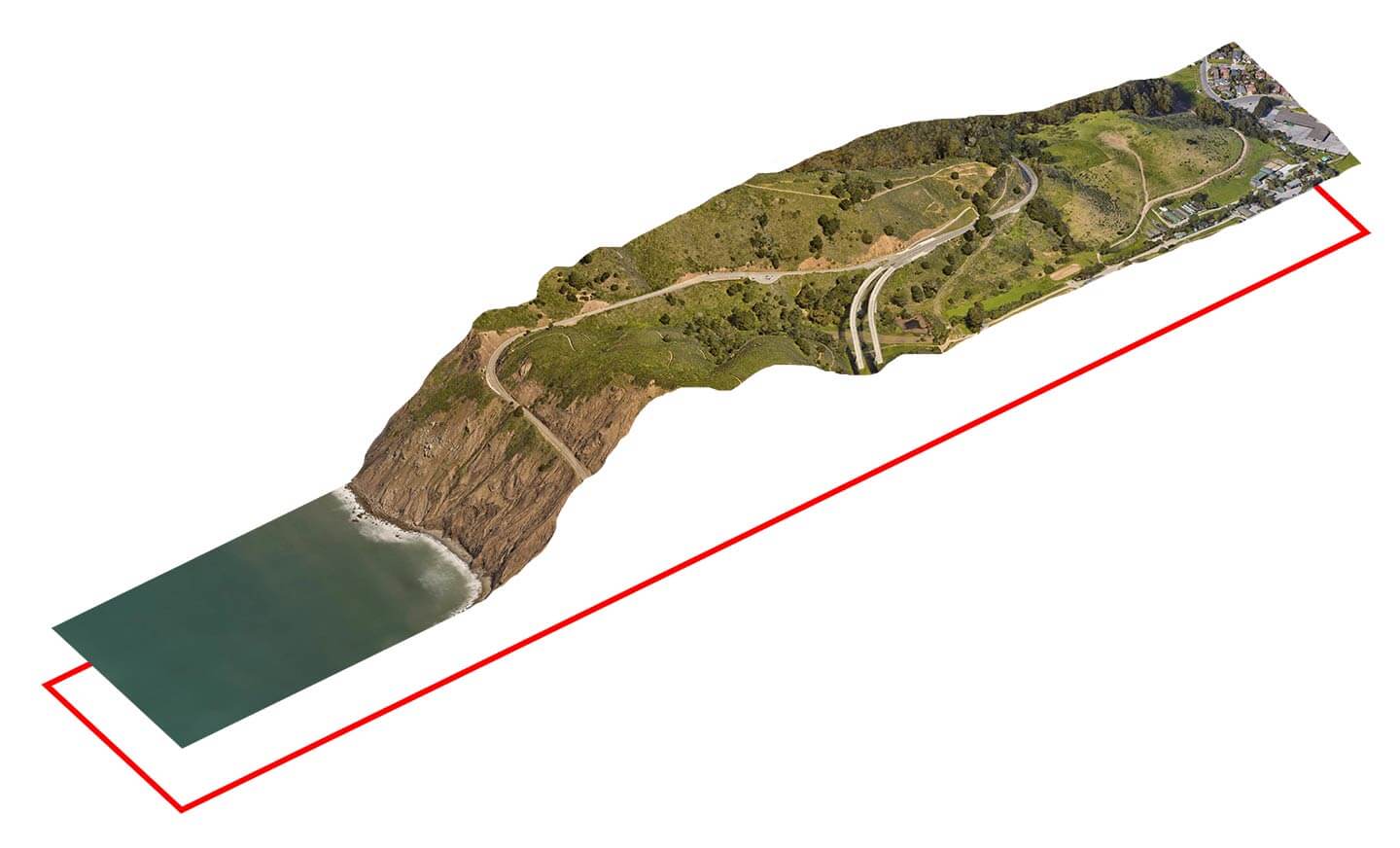
Figure 7: Copied boundary line forms the bottom of the section cut.

Figure 8: Solid fill with a layer mask on each side of the cut.
An earth/dirt texture was brought in, and oriented to the faces of the cut ground using the distort tool. The position and outline of those textures is seen in figure 9. The layer masks from the previous steps was copied over to the texture layers (click and drag mask from one layer to another while holding down alt). At the ocean, more of the textures were erased to make room for a water texture. (figure 10).

Figure 9: Terrain with textures sides.

Figure 10: Textures at the ocean erased to make room for water.
A water texture was masked in between the ocean surface and cut ground. Hue/saturation, levels and brightness/contrast were applied to darken the cut ground and add contrast to the Google Earth terrain.

Figure 11: Adjustment layers used to darken cut earth and add contrast to the terrain.
For the last steps, and Photoshop document was brought into InDesign, where labels were added to point out specific places on the map. Illustrator or Photoshop can also be used. There are many ways the final product can be customized to suite your needs.
Figure 12: Finished cross section map.